This week, the team focused on preparing for the upcoming milestone of Soft Opening next week. To get feedback in advance of softs and have enough time to implement the improvements we need to make, we scheduled for our clients to come to the ETC and playtest our project this week, on Thursday, November 13th.
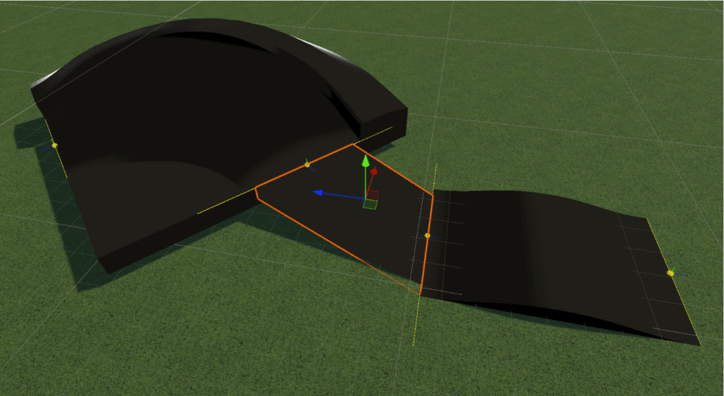
On the track-building side, the biggest priority before the playtest was making sure that the terrain would behave as expected, smoothing properly without clipping into the track pieces. We significantly improved the terrain function and added a button to fix the terrain before testing out the tracks. This process also involved remodeling the berm pieces to smooth them out, since the previous models were too sharp and were causing problems with shaping the terrain around them.
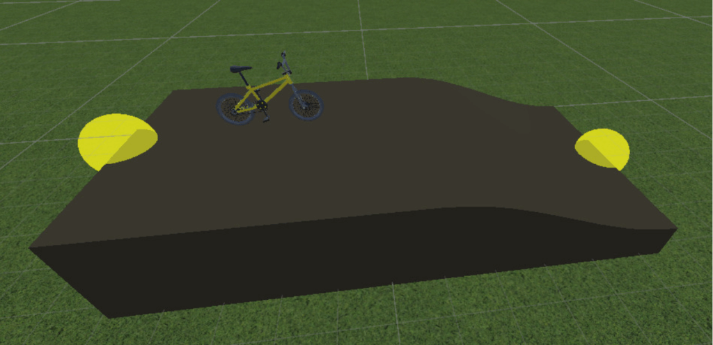
To better match the real-life pump track riding experience, where riders often start on top and drop into the track, we changed the ride starting point piece from an incline with a ramp up to a bike on top of the track in front of a downward slope. We also implemented a tool for adding meshes in between connection points of two track pieces, so that players have much more flexibility in building. This way, they no longer need to feel restricted by the way that the track piece models are designed to snap together. We also began modeling some additional pieces, such as one where the track splits into two paths, so that our users can more easily design curved paths and closed loops. At the moment, there are still some issues with the mesh generated by the line tool, and it only generates straight, rectangular paths between the two points. We will continue iterating on this function, working to create smoother connection paths with Bezier curves, in the next weeks. In the meantime, we tested these improvements with our clients this week.
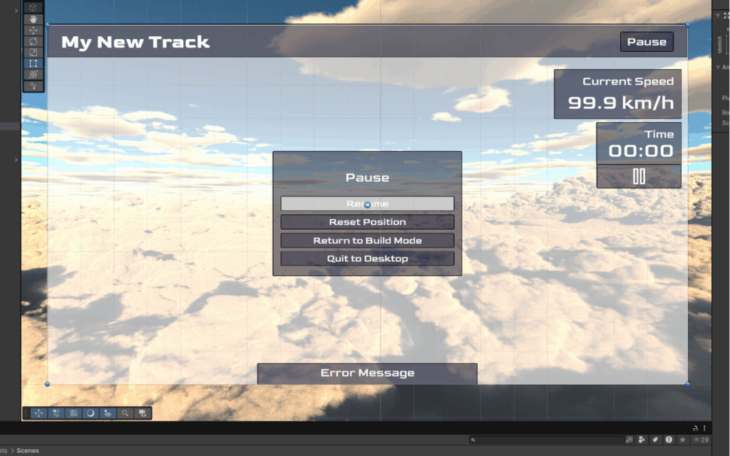
We iterated on and completed the UI design for both the track building and track riding portions of the application. The buttons at the top of the screen for saving and testing out the track were made more obviously clickable, and the toolbar was hooked up with the code to support modes for moving around the area, adjusting track pieces, and using the line tool to draw connection meshes.

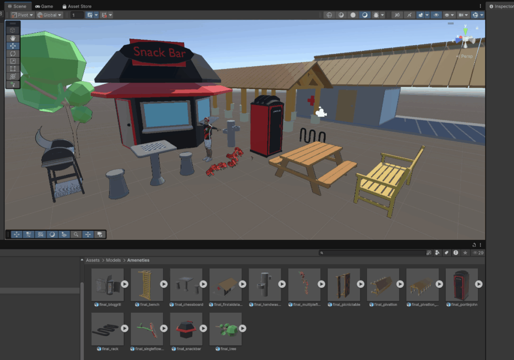
Our artists are continuing to work on enhancing the aesthetics of the project. We created even more models of amenities that can be added to the park areas around the pump track.
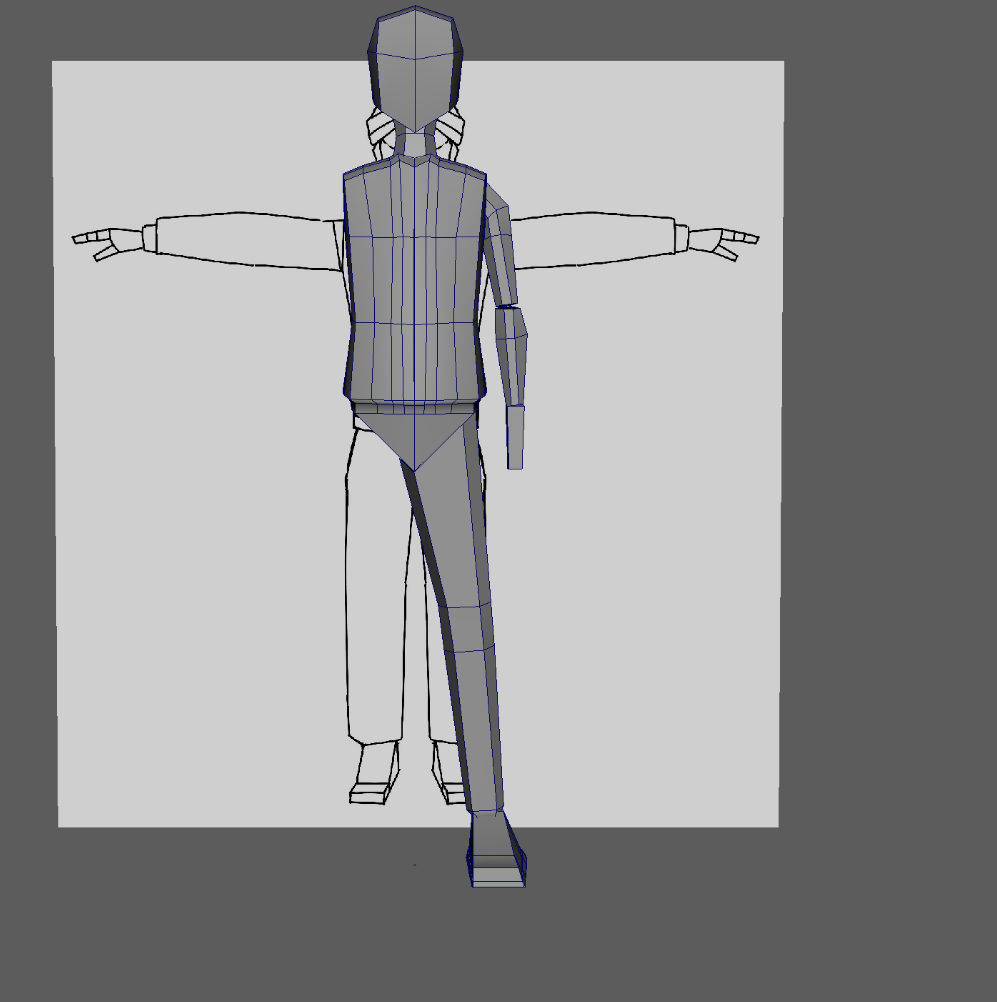
We are also still working on creating a character model to replace the placeholder from the bike physics package. The new character will be more clearly a child around ages 10-15, and we will make them visibly black, to provide representation for our clients and target audience, who would like to see themselves in this character.
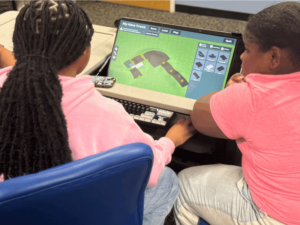
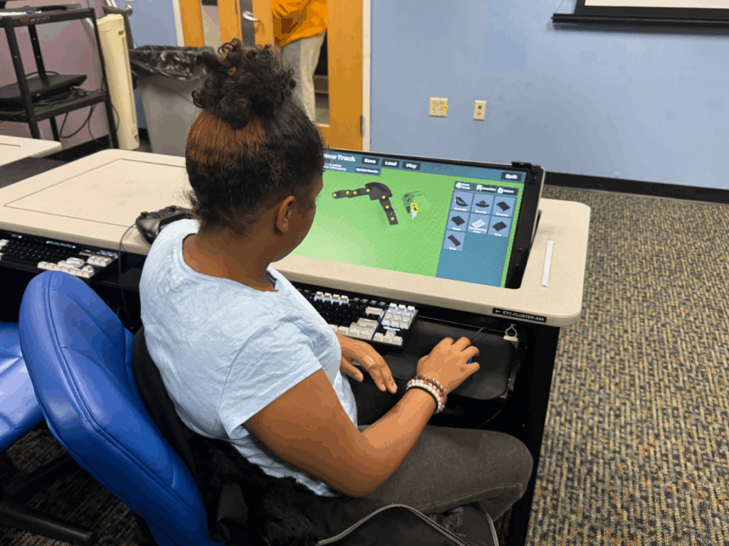
During our playtest with our clients this week, we had two groups of students from the Ruach Bicycle Club work together to try out building and riding on pump tracks on the current version of our product, which they last saw before halves. The students cooperated well together and could effectively use our building tool to design the tracks that they had in mind, with the agency to pick what types of pieces they wanted to include and how to lay them out on the terrain. We learned about some bugs that we need to fix and other quality of life improvements that we will need to make for the final product in order to make this process as smooth as possible, since the players had difficulty deleting pieces and using some of the features.
Additionally, on the riding side, we noticed that it is still too difficult to stay on the pump track, so the players spent a lot of time just riding around on the flat terrain instead. When we discussed with our clients about how they want to integrate our project into their future workshops, they expressed a desire for more progression and learning in the riding portion, as well as allowing for the students to race each other, so in our next iteration, we will need to keep track of the time it takes to traverse the tracks. We also still need stronger visual feedback on the pumping actions in the riding section. As a team, we discussed some ideas for how we might be able to address these issues with the amount of time we have remaining, but we will need to keep figuring this out next week.


Our custom bike handlebars controller was not ready to be used in the playtest this week, but we are aiming to get it fully assembled and connected to the input system before Soft Opening next week. After last week, when we changed to using the rotary encoder and redesigned how the inside of the box would be laid out, we finally received the new pieces we ordered and could begin connecting everything. We continued working with Dave Purta from the IT team to make decisions related to mechanical and electrical engineering, as well as getting his help with the necessary metalworking and hardware tasks.
First, we connected the rotary encoder to the shaft of the bike handlebars stem using a shaft coupler, which we drilled to get to the right size in order to fit correctly (turns out there’s not enough demand for retailers to directly sell shaft couplers between 6mm and 22.2mm diameter shafts).

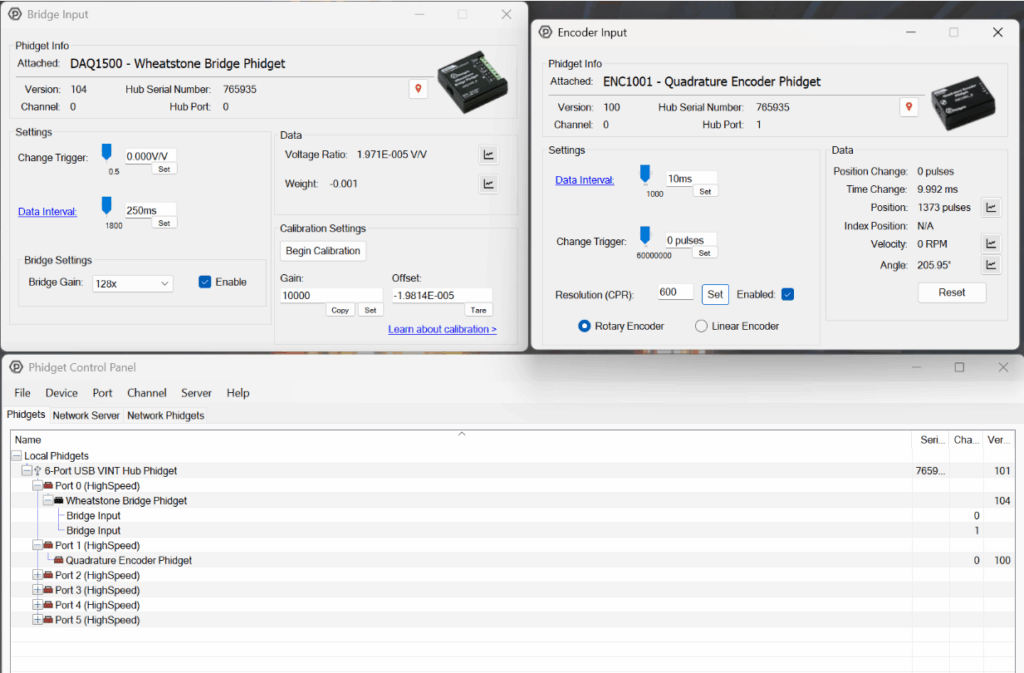
Then, we tested that the data from the rotary encoder and load cell could be properly read by software, using the Phidget Control Panel application.
We also made progress on turning the hand brake levers into buttons. At the start of the week, the plan was to connect the cables that came with the brakes to microswitches, but we realized that it would be difficult to get the right amount of tension that was needed to consistently press and release the buttons. Luckily, we had previously purchased magnetic contact switches to use for this purpose, so we decided to return to testing how we could get those to work. We found that we could drill into the hand brakes, insert a small magnet on the inside, and connect the contact switch sensor on the outside of the brake in a way that would get triggered when the brake was pulled. We still need to finish putting this together, but it’s a great first step to know that this method will work.


With all the pieces that we need to make the controller finally available to us, we could measure what the new size of the box’s interior would be, and we found that it is now too big for us to easily 3D print the enclosure like we were planning to, so we had to quickly pivot to finding and purchasing a suitable metal enclosure. Once it arrived—thank you, overnight shipping—we drilled a hole in the lid to place the flange-mounted ball bearing unit that would hold the shaft in place and prevent it from leaning. We also marked where the metal plate would need to be positioned on the base of the box in order to center the shaft.

Next week, we will need to secure the metal plate inside the enclosure and figure out a neat way to organize the wires inside the box, leaving a hole that we can run the USB cable out. Here’s what it looked like at the end of this week:
